APPLICATION EXAMPLES
Acceleration in calculation of Discrete Element Method
1. Introduction
Figure 1 shows a fluid grid (fluid cell) created inside the group of particles using this scheme for two- or three-dimensions. The whole domain composed by the group of particles, whose shape is a spherical (three-dimension) or a circular shape (two-dimension), is divided by a tetrahedron shape (three-dimension) or a triangular shape (two-dimension) fluid grid. Each fluid grid is defined by adjoining the volumetric center of the nearest particles (four particles: three-dimension, three particles: two dimension). Fluid grid expresses as a fluid reservoir that exists in gaps (void spaces) between particles. The porosity and fluid pressure; pore water pressure are defined by their volumetric center, and each fluid grid conserves the continuity. Fluid flows through boundaries between each neighboring fluid grids due to the pressure difference. The fluid pressure changes for each fluid grid due to the relative motion of particles and fluid flow through the boundary. A body force, which is calculated by multiplying the fluid pressure by area occupied by fluid, is applied to the particles. Since the contact on the Discrete Element Method uses soft contact approach, the particles are treated as rigid body which allows an overlap between particles. Accordingly, the volume calculation of void spaces is also considered to have overlaps between particles. Figure 2 shows a numerical result on underground flow using this scheme. The difference in void spaces enables to simulate localization of flow.
 *
*
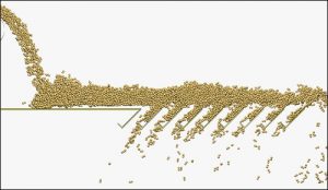
Figure1 Acceleration of calculation in a simulation of particle dynamics.

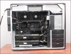
Figure2 GPU board built inside WS.
2. Simulation of debris flow
Figure 3 shows the numerical model. This numerical model is made by connecting horizontal and inclined waterway having width of 0.6m; horizontal waterway of 8m and inclined waterway of 4m with 30 degree slope, and adding a holding section with water sealed gate provided with debris flow particles on the upper section. These dimensions mimic experimental set-up. The model is created by using the two dimensional wall element (a line element) of each horizontal and inclined waterway. The dam model is made by adding line elements as well. The particle holding section and the dam section are each placed with particles modeled as flowing and accumulated debris. For the particles to be placed on the dam section, different colors are used for each 10 cm x 10 cm in order to make movements of particles flowing downwards (particles in debris flow) clear.

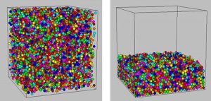
Figure3 Timing test.
List
- Acceleration in calculation of Discrete Element Method
- The Multi-Viscoelastic contact model
- Lattice Boltzmann Method and coupling with Discrete Element Method
- Fixed coarse-grid thermal-fluid coupling scheme
- Particle-fluid coupling scheme considering the pore water pressure.
- 一次元ドリフトフラックスモデルを用いたレアアース泥揚鉱システムの性能計算
- 間隙水圧を考慮した粒子-流体連成スキームの適用事例