APPLICATION EXAMPLES
Fixed coarse-grid thermal-fluid coupling scheme
1. Introduction
The Fixed coarse-grid thermal-fluid coupling scheme solves the continuity, Navier-Stokes (N-S) and thermal energy equations numerically in Eulerian Cartesian coordinates, then derives pressure, velocity vectors and temperature for each fixed cell by considering particle existence. On the other hand, driving forces and thermal energy from fluid are applied to the particles as external body forces and a source term in the force-displacement law and the heat transfer calculations, respectively.
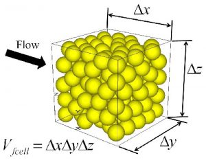
Figure1. Fluid flow through particle assembly.
Figure 2 shows cells used in the thermal-fluid scheme, for the two-dimensional case. The porosity, pressure and temperature are defined at the center of scalar cells. Staggered cells, which are shifted a half size relative to the scalar cells in each direction, are used for discretizing the momentum equations, so that the fluid velocity in each direction is defined at the boundary of scalar cells. The properties of particles used for interaction force, such as velocity of particles, are averaged in each staggered cell. The particle diameter and temperature are averaged in each scalar cell to calculate interaction term of thermal energy. In order to take account of boundary condition, extra cells exist at both ends in each direction.
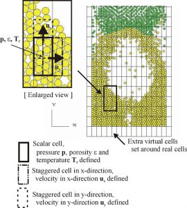
Figure 2. Scalar cell and staggered cell (tow-dimensional case).
Figure3 shows an application example; a general view of particles dynamics and fluid velocity vectors for 5 seconds from the initial stage in a container. Color of each particle shows its temperature. Also, figure4 shows results in the case of fixed particles for comparison. In the case of fluidized particles, the gas lifts particles near the injection, then particles migrate within the box, and the temperature of particles is gradually increased by forced convection and conduction heat transfer from the injection point. Compared with the case of fixed particles, the thermal energy is distributed well within the box. On the other hand, the supplied thermal energy is much more concentrated on the air injection point in the case of the fixed particle case.
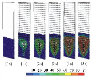
Figure 3. General view; transient of particle temperature and fluid velocity vectors (in the case of fluidized particles).
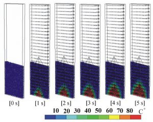
Figure 4. General view; transient of particle temperature and fluid velocity vectors (in the case of fixed particles).
2. Application on Methane hydrate resource development
The Fixed coarse-grid thermal-fluid coupling scheme were applied to study flow assurance of methane hydrate inside pipes in the production system during the collection of methane hydrate. In this application, phase-change algorithm and a bonding model were embedded.
Figure 3 shows the phase-change model. A thin film of methane hydrate formed due to phase changes is damaged by mechanical force, causing new interface between methane gas and water to appear, which its reaction seems to advance successively, but because tracking this process adds complication to the calculation, here we are going to assume that the reaction progresses due to the changes of thickness of the film of methane hydrate.
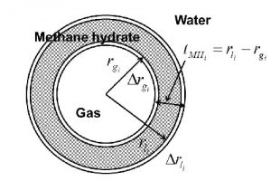
Figure 5. Phase-change model of methane hydrate particles during the flow.
Figure 6 shows the flowchart of phase-change algorithm of methane hydrate. First of all, from the pressure and temperature of each fluid cell, whether it’s in sub-cooling state or in a state with stable methane gas and water are evaluated. The calculation is proceeded by the following method.
In the sub-cooling state, all particles inside a fluid cell are examined whether each particle is constituted by methane gas or not. If methane gas is not detected, that particle does not go through phase-change because it is only constituted by particles of methane hydrate. On the other hand, when the methane gas is detected, changes in mass by the phase-change from methane gas and water to methane hydrate are calculated, as well as porosity change due to phase-change, width of methane hydrate film and the density of particle, and heat energy from latent heat. Then, the porosity change as well as heat energy from latent heat are applied as a source term to continuity and heat energy equations for fluid.
On the other hand, in the case of stable state of methane gas/water, we check whether each particle is constituted by methane hydrate or not. If methane hydrate isn’t found, in other words the particle is constituted of only methane gas, the methane gas particles are modified by pressure and temperature, and change in volume is applied to the continuity equation for fluid. When methane hydrate is found, the phase-change happens from methane hydrate to methane gas, so for this calculation process, the same logic as where the methane gas exists in the sub-cooling state is applied.
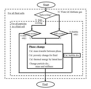
Figure 6 Phase change algorithm and flow chart
Of the re-generated methane hydrate particles, the particles with greater particle concentration are condensed together as particles, or it seems to attach to production system components. There, inside the motion calculation of particles in the DEM, a bonding force is taken into effect when the particle connects to one another or when the particle touches the wall (Figure 7). This bonding force preserves not only tensile resistance and shear resistance, but also bending and twisting resistance.
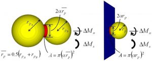
Figure 7. Bonding model
In order to examine the flow assurance inside the production system components by gathering the re-created methane hydrate by pressure reduction method, a simulation (Figure 8, numerical model) was made inside the horizontal pipe used to lower the water level of the production well. Figure 9 shows time transient of the porosity εof central part of numerical model (colored in red in Figure 6) and the sub-part (lower to higher ε1, ε2, ε3, ε4) during particles with bonding force that flows inside the rectangular pipe. When the calculation started, the particles distributed equally inside numerical model, move in the direction of the flow, slowly towards the upper direction. About 2 seconds after the starting, almost all are accumulated and moved towards the upper pipe. In the case of flow with particles having contact force, porosity changes in time , and particles flows as a mass of particles attached together. Therefore, it was found that by adding a contact force to either between particles, or between particles and the wall, the contact model was able to reproduce condensation; attaches to each other and the porosity change inside the duct.
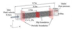
Figure 8. Numerical model.
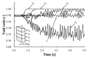
Figure 9. Result of calculation (particles having adhesive force).
References
1). Shimizu, Y., Three-Dimensional Simulation Using Fixed Coarse-Grid Thermal-Fluid Scheme and Conduction Heat Transfer Scheme in Distinct Element Method, Powder Technology, vol.165, pp.140-152, (2006).
2). Shimizu, Y. et al., A numerical study on flow assurance of methane hydrate production systems – coarse grid thermal-fluid coupling scheme in Discrete Element Method with phase change algorithm -, J. MMIJ, Vol. 129, pp11-20, (2013).
List
- Acceleration in calculation of Discrete Element Method
- The Multi-Viscoelastic contact model
- Lattice Boltzmann Method and coupling with Discrete Element Method
- Fixed coarse-grid thermal-fluid coupling scheme
- Particle-fluid coupling scheme considering the pore water pressure.
- 一次元ドリフトフラックスモデルを用いたレアアース泥揚鉱システムの性能計算
- 間隙水圧を考慮した粒子-流体連成スキームの適用事例